EBMC – A Short Tutorial
Introduction
We assume that you have already downloaded the EBMC binary on your system. If not, please download the EBMC binary from here.
Given a synthesizable hardware design in Verilog at register transfer level
(RTL) and safety or liveness properties given in a property specification
language such as SystemVerilog
assertions, EBMC verifies the correctness of the design with
respect to the property. EBMC can perform both bounded and
unbounded verification. In this brief tutorial, we demonstrate how to apply
EBMC to Verilog designs for bounded and unbounded verification.
Checking a Combinational Circuit Using EBMC
Let us consider a simple combinational circuit example1.sv. It implements a two-bit adder. The design comes with a test harness, which includes an assertion. The assertion checks the result computed by the adder.
module my_add(input a, input b, output [1:0] y);

  assign y[0]=a^b;
  assign y[1]=a&b;

endmodule

module main(input a, input b);

  wire [1:0] result;

  my_add adder(a, b, result);

  assert property (a+b==result);

endmodule
The following command is used to run EBMC to verify the correctness of the combinational circuit.
ebmc example1.sv --top main
Observe that we have specified the name of the top-level module
using the --top option.
In response, EBMC reports "SUCCESS" for the property, which means
that it holds for any inputs a and b.
Property Specification on the Command Line
EBMC also allows to specify a property on the command line. For example1.sv, we can specify our property on the command line as given below.
ebmc example1.sv --top main -p "a+b==result"
Bounded Verification of a Sequential Circuit Using EBMC
The behavior of a sequential circuit not only depends
on the inputs but also on the state of any registers or flip-flops. We can
instruct EBMC to perform bounded verification of a sequential circuit by
giving the --bound command-line option. EBMC then tries to
prove or refute the properties given as assertions in the main module within
that bound. To this end, EBMC unwinds the transition system up to the
user-specified bound.
To illustrate bounded verification, let us consider a
simple Verilog circuit for counter design named example3.sv. The design contains two SystemVerilog
properties. The first asserts that the least-significant bit of the counter flips when
the input named enable is high. The second checks whether
the counter can reach the value three.
module counter(
  output [7:0] out,
  input enable, input clk);

  reg [7:0] state;
  assign out = state;

  initial state = 0;

  always @(posedge clk)
    if(enable)
      state = state + 1;

  assert property (enable && state[0] |-> ##1 !state[0]);
  assert property (state!=3);

endmodule
Now, run EBMC command to verify the counter circuit for ten transitions as follows:
ebmc example3.sv --top counter --bound 10
EBMC reports that the first assertion holds, and that the second assertion has failed, as follows:
** Results:
[counter.property.1] always counter.enable && counter.state[0] |-> ##1 !counter.state[0]: SUCCESS
[counter.property.2] always counter.state != 3: FAILURE
Understanding EBMC Counterexamples
Whenever EBMC refutes a property, it computes a counterexample path starting
from the initial state and leading to the error (bad) state.
Recall that the second property of example3.sv is failing.
We can ask EBMC to output the counterexample trace by specifying the --trace
command-line option. We obtain the following trace:
Transition system state 0
----------------------------------------------------
  counter.state = 0 (00000000)
  counter.out = 0 (00000000)
  counter.enable = 1

Transition system state 1
----------------------------------------------------
  counter.state = 1 (00000001)
  counter.out = 1 (00000001)
  counter.enable = 1

Transition system state 2
----------------------------------------------------
  counter.state = 2 (00000010)
  counter.out = 2 (00000010)
  counter.enable = 1

Transition system state 3
----------------------------------------------------
  counter.state = 3 (00000011)
  counter.out = 3 (00000011)
  counter.enable = 0
Observe that counter has reached the value three in the final state of the trace.
Using the VCD Dump
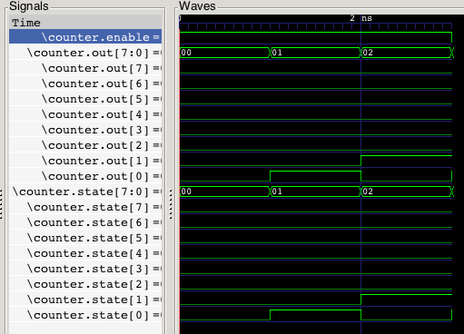
The counterexample trace from EBMC can be saved in a vcd file
and can be viewed with any waveform viewer such as
gtkwave.
The command to dump the counterexample trace for the second property in
example3.sv is given below (one line).
ebmc example3.sv --module counter --bound 10 --vcd example3.vcd
This generates a file example3.vcd, which is visualized by gktwave as follows:

Specifying the Reset Logic
Let us consider a variant of the Verilog model, given as example4.sv. In this variant, the initialization of the registers is performed using an active-high reset signal.
module counter(
  output [7:0] out,
  input reset, input clk);

  reg [7:0] state;
  assign out = state;

  always @(posedge clk)
    if(reset)
      state = 0;
    else
      state = state + 1;

  assert property (reset |-> ##1 state==0);
  assert property (reset |-> ##2 state==1);

endmodule
Now, run EBMC command to verify the counter circuit for a bound of ten as follows:
ebmc example4.sv --top counter --bound 10 --trace
The first property in the module checks that the reset signal correctly sets the value of the counter to zero. It passes. The second property in the module asserts that the counter reaches the value one after two clock ticks after the reset cycle. Perhaps unexpectedly, this property fails. This is due to the fact that the reset signal is an input, and thus, may take arbitrary values. In particular, reset may be active in the second time frame.
We can instruct EBMC to assume that the reset signal
is driven in the usual fashion using the --reset command-line
option. The design uses an active-high reset signal, so the reset expression is
reset==1.
ebmc example4.sv --top counter --bound 10 --reset reset==1
The second property now passes as well.
Co-verification and equivalence checking tool
If you are interested in hardware/software co-verification or C-RTL equivalence checking, please use our tool HW-CBMC.